Being virtually a horizontal dipole, this aerial may show a performance superior to that of the quarter wave whip when working to base stations using horizontal polarization.
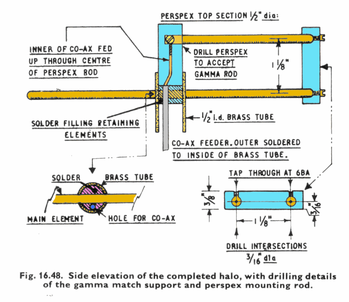
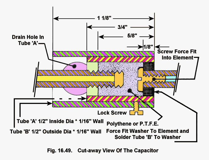
Standard halo aerials tend to be uncomfortably large even on 144 Mc/s, and this led to the design of a miniaturized capacity loaded halo, the constriction of which is illustrated in Figs. 16.47, 16.48 and 16.49.


The most important part of the design is the tuning capacitor, and this must he constructed with care. To allow sufficient threads to be cut in the wall of the Outer adjusting sleeve, this is tapped at 6B.A. It should be noted that the inner of the two tube sections making up the capacitor is secured to one end of the circular element by a screw which force fits into the bore of the tube. The polythene or P.T.F.E.. lining of this inner tube is fitted to the other end of the circular element by cutting a thread on its outside diameter and force screwing the lining over this thread. To assemble, the outer sleeve of the capacitor is slipped over the inner sleeve, the P.T.F.E. end of the element sprung away from the sleeve end, and then inserted into the bore of the capacitor inner sleeve.
The gamma match is of the same dimensions as would be used on a full sized version, that is approximately 4.5 in. long. In setting the system up the outer sleeve of the capacitor is used to bring the aerial to resonance, and then, in conjunction with an S.W.R. bridge, the gamma match is set for minimum S.W.R.
Contrary to what might be expected, the mini-halo is not particularly frequency conscious, and tuning 2m does not show any decrease in signal strength from one end of the band to the other.
MONITORING FIELD STRENGTH
Under mobile conditions it is highly desirable to be able to monitor the field strength of the signal radiated by the transmitting aerial. Using a field strength meter within the saloon of a car can give completely misleading indications due to the R.F. currents circulating within the car body. {ideally a small external aerial is required, but the idea of fitting yet another aerial is generally unacceptable.
A neat solution to this problem is to use a wing mirror as the field strength meter aerial by insulating such a mirror from the frame of the car. The method is illustrated in Fig5 16.50. For best results the wing mirror metal parts should be made from brass as the base metal. The lead from the solder tag on the underside of the mirror to the F/S meter is a coaxial lead, the screening of which is either earthed at the indicator end in the case of V.H.F. operation, or connected to the inner for the H.F bands.
MOBILE SAFETY
While it is to the credit of mobile operators that no accidents have been attributed to the operation of mobile radio equipment, In the event of such an accident there could be no valid defence. One item which could cause such an accident is the fist microphone and its trailing lead. Anyone who has foolishly tried to negotiate a sharp turn, or a roundabout while clinging to a microphone with a press-to-talk switch will readily verify that the hand held microphones can in Ttese circumstances be particularly dangerous. One microphone arrangement which goes a long way to solving this problem is that used in some radio-taxis and in which the microphone is fitted to a length of flexible tubing. Even this is not perfect for while it leaves both hands free for control of the vehicle, the head has to be maintained in